Hydraulic modellers use scenarios to answer “what if?” questions without duplicating entire models. Sometimes those questions are operational (a burst, a valve closure, a temporary rezoning). Other times they’re long-term planning (staging upgrades over 5-year periods, testing when projects need to land, and comparing pathways).
We’re working in the open and building epanet-js with the community. Scenario management is both a key feature and a complicated one that needs to fit how models are used to support water utilities decision making, so we’re publishing this request for comments early before we lock in the details.
This document lays out:
- What we mean by scenarios (and the key moving parts),
- How scenario management is commonly implemented in other tools,
- The approach we’re proposing for epanet-js
- How you can get involved
Why scenarios matter in hydraulic modelling
Most teams don’t use scenarios because they’re “nice to have”. They use them because once a model is in active use, the alternative is messy: people duplicate files, make edits in multiple places, run the analysis, and then struggle to remember (or prove) what changed, when, and why.
Scenarios give you a way to keep one baseline network and represent alternatives as structured variations. That makes day-to-day work easier: you can test ideas without overwriting the baseline, repeat an analysis later with the same assumptions, and work in a single project instead of managing a folder full of near-identical copies.
In practice, scenario work usually falls into two broad families.
Operational scenarios (short-term, one-off analyses)
These scenarios are used to understand a change to the current network, usually starting from a “current-day” baseline (often an average day or calibrated operational model). The edits are typically targeted: a burst or shutdown plan, a valve closure, a temporary rezoning/backfeed, a development enquiry, or a seasonal operating strategy. Just as important as getting an answer today is being able to reproduce it later, with a clear record of what was changed.
Master planning scenarios (long-term, staged change)
These scenarios are used to understand how performance changes over a long horizon as demand grows and the network expands. The model evolves through staged upgrades (often in fixed blocks like 5-year periods), and teams test different options and timing for reinforcements. A big part of the work is exploring uncertainty in project sequencing: what happens if a pump upgrade is delayed, if a transfer main is brought forward, or if you try a different pathway entirely.
Both families share the same core need: compare model states without losing your baseline. Where they differ is what they stress in your workflow. Master planning leans on staging and growth over time, usually with a deep nested structure, while operational work leans on speed, clarity, and repeatability for small changes in your network.
The moving parts of a scenario
A “scenario” isn’t one type of change. It’s a container for several kinds of changes that affect how the model behaves and what results you get. Different tools draw the line in different places, which is why scenario systems can feel inconsistent across platforms.
In general, scenarios are made from the following building blocks.
Active topology
Active topology defines which assets are “in play” in a scenario.
This is commonly used to represent:
- what exists now vs what is built later (planning),
- alternative options (two possible pipe routes),
- decommissioning or abandoning old assets,
- temporarily taking assets out of service.
Active topology can be set manually by enabling or disabling individual assets, by using selection lists, or by running rule-based queries that include or exclude assets.
Attributes
Attributes are changes to the properties of model elements. These usually fall into two categories:
- Physical properties: pipe diameter, roughness, minor loss, emitter settings, pump curves, etc.
- Operational properties: default statuses, valve settings, pump settings, and similar “how it behaves” values.
Controls
Controls represent operational logic: when pumps switch, when valves change status, how tanks are managed, and how supply is routed under different conditions.
Demand
Demand changes can take several forms:
- Scaling existing demand (e.g., infill growth, max day multipliers),
- Swapping demand patterns (average pattern vs max day pattern),
- Manual edits (localised changes at specific nodes),
- One-off large demands (major sites, temporary draw, special events).
Demand handling is one of the areas where a scenario system needs to stay very clear about what’s inherited versus what has been changed, because small changes can have big network-wide effects.
Simulation settings
Simulation settings control how the model is run for a given scenario.
They can be used to change run configuration (duration, hydraulic and reporting timesteps), adjust solver parameters (tolerances, maximum trials, and related options), and define the simulation type.
In practice this is where you decide whether you’re running steady-state hydraulics, EPS, a fire flow test, or a water quality analysis (for example, water age or chlorine).
Connectivity and geometry
Connectivity and geometry define the network graph: where assets are located and how they connect. They matter in every scenario, but they also behave differently from “normal” scenario data in inheritance based systems because edits can break downstream assumptions (what connects to what, which assets exist, and what other changes are attached to them).
That’s why geometry/connectivity can be treated as a special case. The next section explains the core problem: once geometry can vary between branches, merging and inheritance get messy fast.
The geometry and connectivity problem
Most scenario systems handle attribute changes cleanly: a child can override a value and the parent can pass updates downstream. Geometry and connectivity doesn’t work like that because they change the structure and identity of the network.
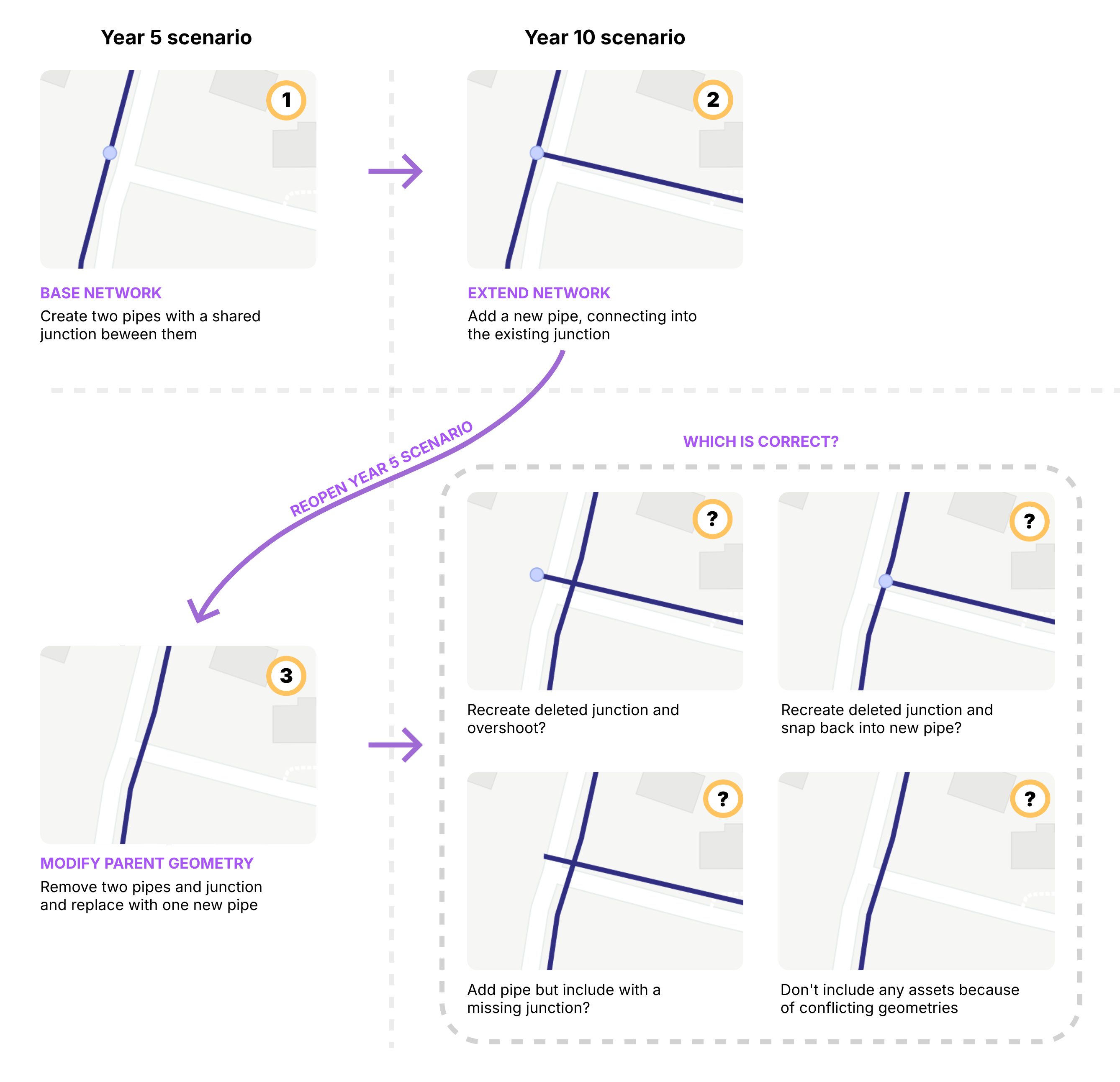
Imagine you have a simple intersection where two pipes meet at a junction in your “Year 5” scenario. You then move on to a “Year 10” scenario and extend the network, creating a tee intersection by connecting a new pipe into that same junction.
Later, you go back and modify your “Year 5” scenario — deleting the original two pipes and junction and redrawing them on the other side of the road. What happens now to the geometry that was defined in the child scenario?
Do you recreate the deleted junction so the new pipe still has full connectivity, but is now disconnected from the original pipes? Or do you try to be clever and automatically reconnect it to the new geometry?
Alternatively, do you bring the pipe across with broken topology and a missing junction? Or, if there are conflicts, do you drop the asset entirely and raise an error?
There isn’t a single merge rule that’s always correct.
In practice, tools avoid this in one of two ways. Some keep geometry global so there’s one shared base geometry across scenarios, and scenarios mainly store differences in properties and operations. Others avoid inheritance by working in discrete datasets that are copied and edited in isolation, so geometry changes don’t need to merge — but fixes don’t automatically propagate either.
With that backdrop, most hydraulic modelling tools end up in two broad camps for scenario management.
How scenario management is typically done today - and where it breaks
Most hydraulic modelling tools sit in one of two camps: Inheritance-first (building scenarios by layering changes) or Dataset-first (building scenarios by assembling cloned tables).
WaterGEMS / WaterCAD style
Inheritance via Alternatives
In this ecosystem, scenarios are built using a parent-child structure. A child scenario inherits data from its parent unless it is assigned a specific Alternative.
Alternatives act as containers for changes. They don’t duplicate the whole database; they list only the elements that have been modified. When you run a scenario, the engine starts with the base data and applies the overrides found in the active alternatives.
Where it breaks:
The “Whole-Element” Override Trap: While alternatives are meant to store changes, they function as whole-element overrides. If you modify a pipe’s diameter in a Physical Alternative, the software captures all physical attributes for that pipe (including roughness and minor losses) in that alternative.
As a consequence you effectively sever the inheritance for that element. If you later update the pipe’s roughness in the parent scenario, the child won’t see it because it is using its own local copy of all the element’s attributes. You end up with “stale” data simply because you touched a different attribute on the same asset.
To avoid the complexity of merging network shapes, geometry is global in WaterGEMS/WaterCAD. Every scenario shares the same base geometry. Future assets are typically handled via Active Topology.
If you’re unaware of this global state, and especially if you have “Hide Inactive Elements” turned on, you can end up with a disconnect between what you see and what you think is happening.
The two main traps with this global geometry are:
- Assumed Deletions: If you have “Hide Inactive Elements” turned on and you delete a pipe in a future scenario, the pipe will disappear but you aren’t removing it from the database - you are just marking it Inactive.
- Global Shifts: If you move a node to align with a new road, you are moving it in every scenario.
InfoWater style
Dataset Assembly
InfoWater leans heavily on a dataset workflow. Instead of inheriting changes, you clone entire database tables (e.g., a specific Demand Set or Pipe Set). You then build a scenario by telling it which sets to assemble.
There is no direct inheritance link between the data tables themselves. Once you clone a dataset, it is an independent copy.
Because you are working with copies, you are free to edit geometry in one scenario without affecting others. However, this independence becomes a liability when you need to fix a mistake.
If you discover a connectivity error in your base model (e.g., a pipe connected to the wrong junction), fixing it in the base does nothing for your other scenarios if you have created separate pipe sets. You must manually propagate that fix across every dataset copy you have created. As the number of scenarios grows, keeping the data sets consistent becomes a manual maintenance burden.
The common friction
Monolithic bundles
Despite their differences, both tools share a major structural frustration: Group by Type, not by Project.
In both systems, data is categorized by its technical type (Demand, Control, Physical) rather than its logical purpose (e.g., “Northville Subdivision” or “Pump Station Upgrade”).
A real-world project usually requires changes to pipes, demands, and controls simultaneously. However, the software forces you to split these changes into separate buckets (a Demand alternative, a Control alternative, etc.).
Consequently, each project in your scenario becomes tightly coupled with others in the same bucket. If you want to move “Project A” from Year 5 to Year 10, there is no easy way to move it. You have to open the Year 5 Demand alternative, unpick the Project A demands, move them to the Year 10 alternative, and then repeat the process for controls and pipes.
The epanet-js proposal
Our goal is not to force you into a specific workflow but to align with how models naturally evolve. Real-world networks change over time—pipes age, demands shift, and new pumps are installed.
Our proposal separates this “evolution” from “experimentation” by treating History (the timeline of truth) and Scenarios (experimental branches) as distinct but connected concepts.
The timeline
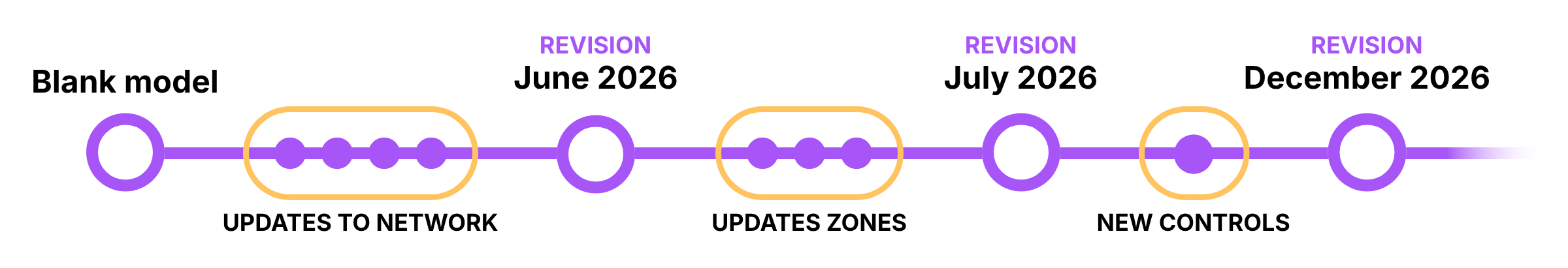
Every model has a main timeline representing the “calibrated truth.” As you maintain your model (updating demands, controls and amending new infrastructure), you move this timeline forward.
Instead of overwriting your work or saving “Model_v2026.01_FINAL.net”, epanet-js will track this as a linear History of named Revisions.
- The Baseline Moves Forward: The “Main” model is always being updated to reflect the current day.
- Revisions as Anchors: You can tag specific points in time (e.g., “July 2025 Calibration”).
This creates an audit trail of how the physical reality of the network has changed over time.
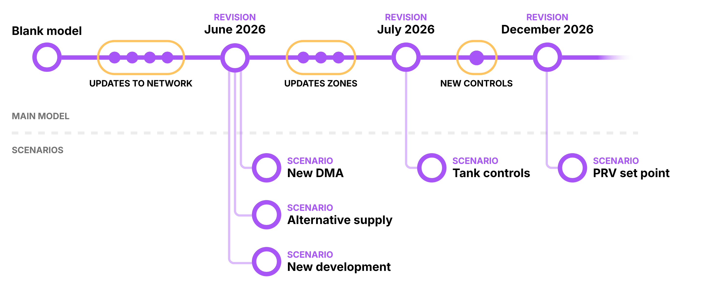
The branch: scenarios
A Scenario is a branch created from a specific Revision in history that allows you to test changes to the network without affecting the main branch.
Crucially, when you create a scenario, it is pinned to that moment in time to avoid the geometry and connectivity issues previously discussed in an inheritance based model. The scenario becomes a stable snapshot. You can continue updating the main model (changes in operational settings, adding new infrastructure) without the risk of breaking your scenario.
When you enter a scenario, you are referencing the Revision as a Read-Only Baseline. You are not copying the model; you are simply defining a new workspace that references that fixed point in history.
For some scenarios, keeping a fixed baseline is essential. It ensures you can always return, rerun the analysis, and understand the decisions that were made at the time.
In other cases, you may want a scenario to move forward as the main model evolves. For example, a long-term project that was paused may need to be revisited using the latest calibrated network. epanet-js will support detaching a scenario from its original revision and reattaching it to a newer snapshot, with explicit checks and confirmations to surface any conflicts before the change is applied.
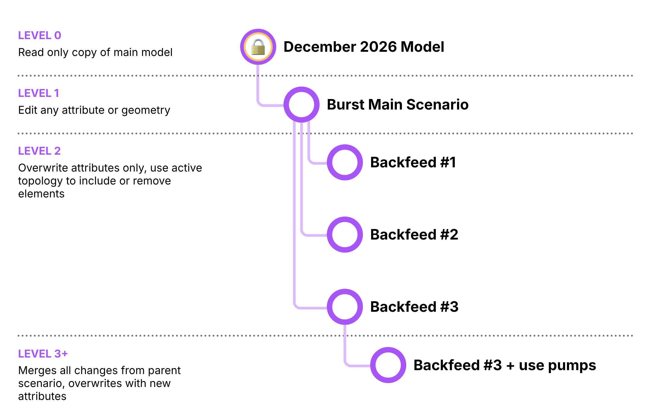
The geometry strategy: The two-level rule
Geometry conflicts (splitting pipes, moving nodes) are the hardest part of scenario management. To solve this without creating a mess of conflicting topologies, we use a structured hierarchy for editing permissions.
Level 0: The Baseline (Revision)
- Status: Read-Only.
- Role: The fixed reference point you are comparing against.
Level 1: The Workspace (First Branch)
- Status: Free Edit (Geometry + Attributes).
- Role: This is where you prepare your experiment. If you are simulating a burst, you break the pipe here. If you are designing a new subdivision with two supply options, you draw both pipelines here and disable them by default.
Level 2+: The Variations (Children)
- Status: Attribute Edit Only.
- Role: These scenarios act as toggles and overrides. You cannot draw new pipes or assets here because the geometry is defined from Level 1. Instead, you use these branches to switch things on and off (Active Topology), overwrite attribute values, change settings, or scale demands.
This structure allows us to handle complex geometry without the chaos of inheritance. You define the physical world in Level 1, and you explore the options in Level 2 and below.
The core unit: change sets
Traditional scenario management in hydraulic modelling tools often relies on multiple layers of alternatives that must be combined to represent a single planning outcome. In tools such as WaterGEMS, a typical master planning workflow might involve separate physical, initial status, and operational alternatives, each duplicated across multiple planning horizons (for example, year 5, year 10, and year 15).
When new infrastructure is introduced—such as a pump station, tank, or pipeline—its full definition is spread across all three alternative types. A single pump may require physical changes, initial status settings, and operational controls, each defined separately but intended to represent one real-world project. If the timing of that project changes later (for example, moving construction from year 5 to year 10), the modeller must manually remove the pump from all associated alternatives at one horizon and recreate those same changes across all alternatives at the new horizon. This approach works, but it is fragile, repetitive, and difficult to maintain as plans evolve.
In epanet-js, scenario management takes a different approach. Instead of splitting changes across alternatives defined by types, all related modifications are grouped together into discrete change sets, organised by project. Each change set represents a coherent unit of work—such as a single pump station, tank, or pipeline—and contains all required overrides for that asset: physical properties, initial statuses, controls, and any active topology changes.
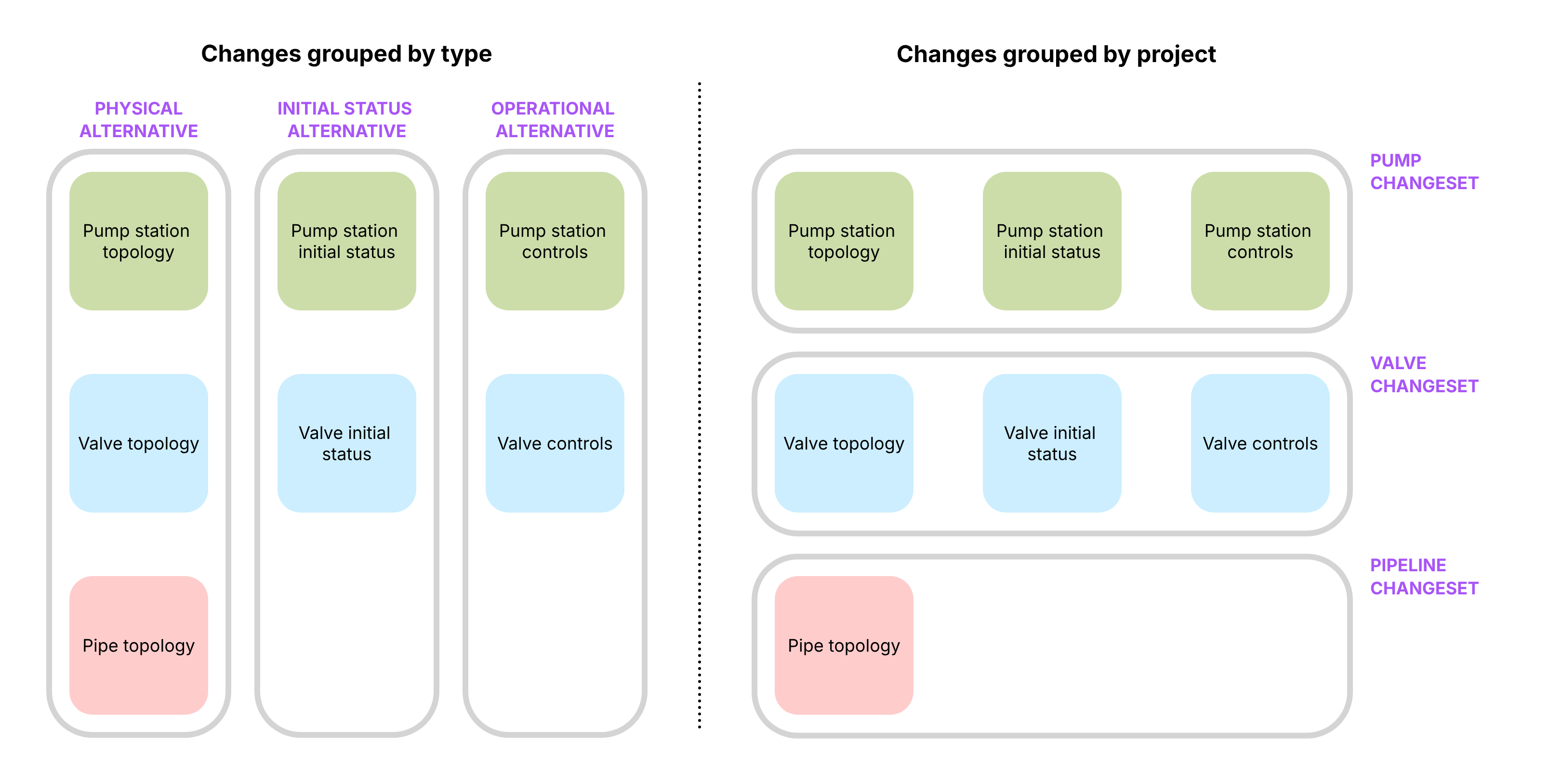
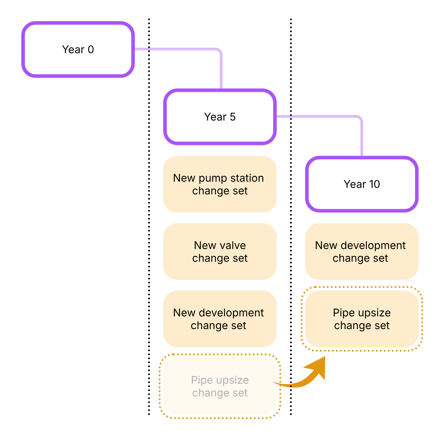
Scenarios are then constructed by composing these change sets. A planning tree might still include year 5, year 10, and year 15 horizons, but instead of redefining infrastructure repeatedly, the modeller simply selects which change sets apply at each point in time. If a pump station is delayed by five years, the modeller moves that pump’s change set from the year 5 scenario to the year 10 scenario. No duplication, no re-drawing, and no risk of leaving behind partial or inconsistent overrides.
By isolating changes into small, self-contained units, epanet-js makes scenario inheritance more explicit, easier to reason about, and far less brittle. Scenarios become lightweight compositions of projects rather than tightly coupled stacks of alternatives. This allows planning models to evolve naturally as assumptions change, without requiring extensive rework or manual synchronisation across multiple scenario layers.
Putting it together: The Scenario Object
If Change Sets are the ingredients, the Scenario is the recipe.
In epanet-js, a scenario is a lightweight object that defines a “Stack” of instructions applied on top of its parent. When you select a scenario, the application builds the model state on the fly by combining:
- The Parent Source: The starting state (either a Base Model or another Scenario).
- The Merging Stack: An ordered list of modifications layered on top:
- Change Sets: (e.g., “Project A Logic”, “Winter Controls”).
- Demand Modifiers: (e.g., “Global Residential Scaling x 1.2”).
- Active Topology Rules: (e.g., A dynamic Query to “Enable pipes constructed < 2030” or a static Selection List).
Decoupling the “Run” from the “Network”
We also treat Simulation Configurations as global objects independent of the network state.
- The Scenario defines the Network Reality (Physical assets, Controls, Demands).
- The Simulation Config defines the Analysis Type (Standard EPS, Fire Flow, Chlorine Decay).
This means a single Scenario Object can host multiple Run Configurations. You can look at a single “Year 5 Planning” scenario and choose to execute it against a “Fire Flow Config” or a “Water Quality Config” without ever duplicating the scenario itself.
Supported workflows
This architecture (history + multi-level editing + change sets) supports the full range of modelling workflows:
The Simple “What If?” (Operational)
- Goal: A quick check of a single operational change (e.g., “What happens if I modify the set point of a PRV?”).
- Workflow:
- Select the current Revision (Read-only Baseline).
- Create a Level 1 Scenario.
- Make your edit (change the outlet pressure of the valve).
- Run and compare immediately against the Baseline.
This investigation may lead to a change in network operations, at which point you would update the main model. Because the scenario remains pinned to a fixed point in time, if you later receive an inquiry about why the decision was made, the original scenario remains available as a record - unaffected by any subsequent changes to the model.
Multi-option response
- Goal: Confirm the capacity of the existing network to supply a new multistory development.
- Workflow:
- Level 1 (The impact): Create a scenario called “Main St Development.” Add the demand into the network and see the impact on the network.
- Level 2 (Capital work options): Create children scenarios to test different upgrades to support the new development under “Main St Development” (e.g., “Option A: Upgrade distribution main” vs “Option B: Rezone to higher pressure”).
- Action: In these children, you only change attributes (e.g. pipe diameters or valve status) to test alternative supply strategies.
Master Planning (Long Horizon)
- Goal: Staging infrastructure growth over 5, 10, or 20 years.
- Workflow:
- Level 1 (The Super-Model): Create a “Master Plan Canvas” scenario. Draw all future infrastructure here (pipes, pumps, new zones) but set their active topology to disabled, tag them with the year they are to be constructed..
- Level 2+ (The Timeline): Create child scenarios for “Year 5”, “Year 10”, etc.
- Action: In each child, use a active topology rules to enable your growing network and demad (e.g. a query to enable all pipes constructed by 2030) and then use Change Sets to switch on the relevant group of assets for each specific time horizon year. Since the geometry resides in the parent, there are no merge conflicts.
- By using change sets for each capital work project (e.g. “Trunk main upgrade”, “Increased pump capacity”) you can move those between the scenarios to find the most efficient combination of capital works and when they’re needed.
Summary
By distinguishing between History (the evolving truth) and Scenarios (branches for experimentation), and implementing a two-level Editing Rule for geometry, epanet-js simplifies the mental model of modelling.
This approach allows you to:
- Maintain a living, updating model of the Current Day network.
- Spin off stable Scenarios that don’t break as the model evolves or become a spaghetti mess of overlapping infrastructure.
- Create dynamic Master Plans by splitting your capital works and growth into individual change sets that you can move freely between time horizons allowing you to find the most efficient use of your planning budget.
Over to you
We are building this for the community, so we want to know if we’re on the right track before we start writing code.
- Does this resonate? Do the “traps” and “frictions” we described match your daily experience, or are we missing the mark?
- What would you change? Is there a specific workflow or “edge case” this proposal doesn’t cover?
- What makes you nervous? Is there anything in this approach that feels like it might get in your way?
Please share your thoughts on our roadmap here: